ABS Module Diagnostics
The first step in diagnosing an ABS DTC (or illuminated ABS light) is to ensure that the ABS module is receiving power. Inspect the ABS fuse(s); they differ by model year, but are identified in your owners manual. If a blown fuse is found replace the fuse, remove any stored DTCs, and test the vehicle. Also verify that the ABS module connectors are secured and that the wiring harness is not damaged. If you are receiving a DTC related to a wheel speed sensor, verify that these connectors are secure and not damaged.
If you are receiving multiple DTCs for the ABS system, the ABS module is likely the problem. However, if you are receiving a single code for a particular wheel speed sensor or rear differential speed sensor, than the sensor is likely the cause of your ABS system troubles. It is very unlikely that all the wheel speed sensors would fail at the same time, but all it takes is one faulty sensor to throw the entire system off course. C1185 is a common code received when an ABS module fails, and it may be accompanied by several additional DTCs since the system is unable to isolate the problem.
Ford F-150 ABS Module Replacement Procedures
Click any thumbnail to view high resolution full-size image with details
• Disconnect the negative battery terminal.
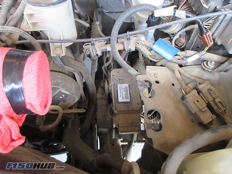
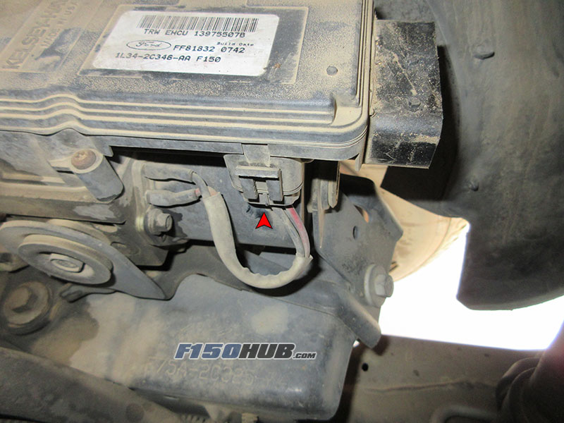
• The ABS control module is located on the driver side beneath the air filter housing. It is mounted to the top of the ABS hydraulic unit. Remove the air filter and any additional items to gain access to the control module. Alternatively, it is also accessible by removing the driver side inner fender.
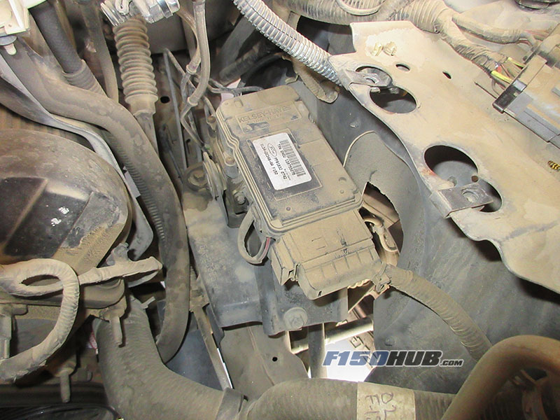
• The ABS module has (2) electrical connectors; a large chassis harness connector and a small connector feeding the ABS hydraulic unit.
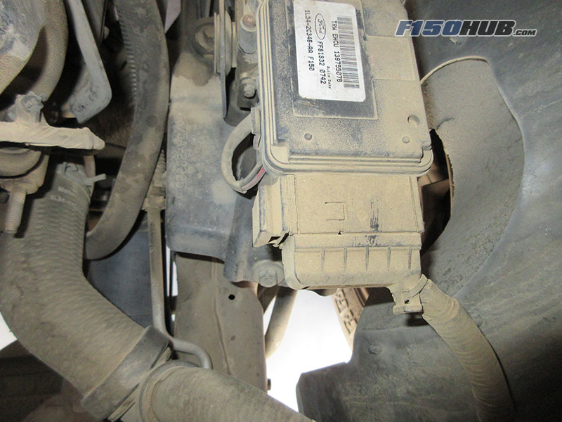
• The large chassis harness connector features a slide lock. To remove, pull the slide lock towards the passenger side of the vehicle while pulling the connector shell outwards away from the ABS module.
• As the slide lock is withdrawn, the connector will travel towards the front of the vehicle in one motion. Position the connector aside to avoid damage while removing the module.
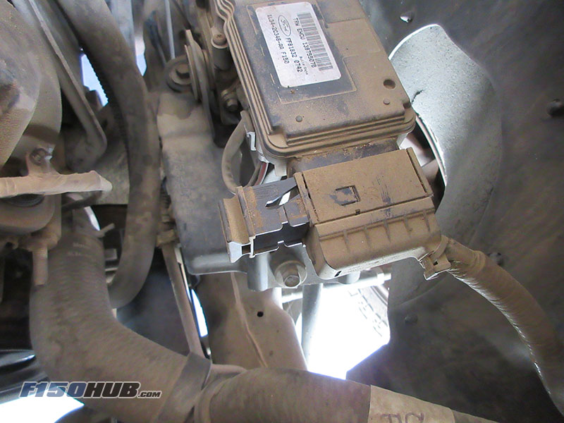
• The second electrical connector is located on the side the module and connects it to the ABS pump/hydraulic unit. Simply disengage the locking tang and pull downwards to remove.
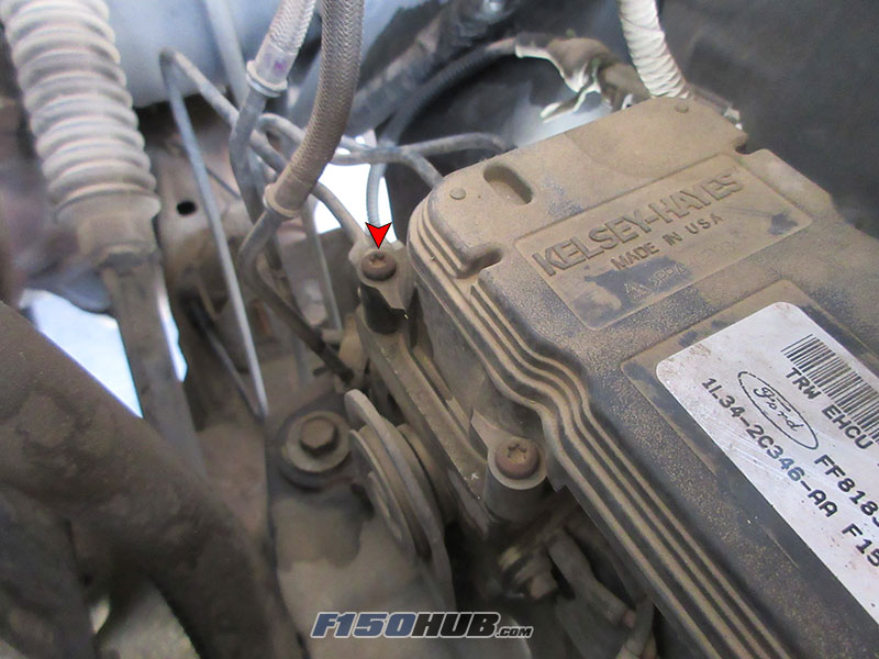
• Remove the (4) bolts securing the ABS module to the ABS pump/hydraulic unit with a T20 Torx driver.
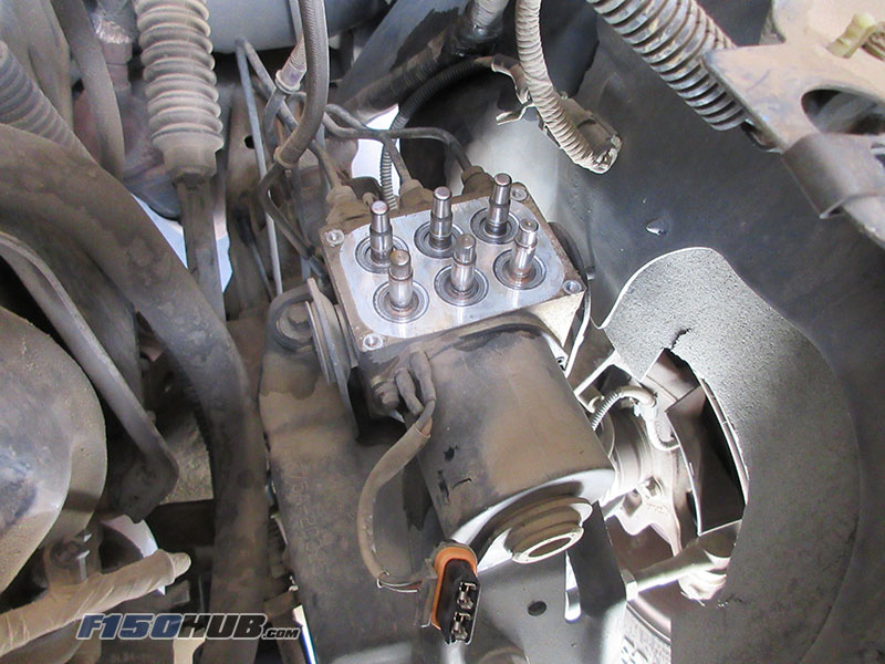
• Carefully pull the ABS module straight upwards to separate it from the ABS pump/hydraulic unit. Cover the exposed solenoids to protect from dust/debris intrusion.
• Installation of the new ABS module is reverse. Be sure to ground yourself and discharge any static electricity before handling the replacement module.
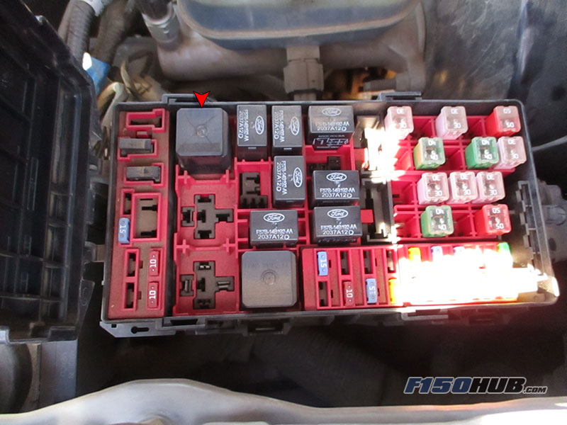
• As an optional step, we highly recommend replacing the ABS fuse and/or relay. The location of these items can be found in your owners manual.